
Choosing between a panel bender and a press brake is not simply a question of which machine is newer, faster or more automated.
The two technologies form sheet metal in fundamentally different ways.
A press brake typically positions the workpiece against a backgauge and forces the sheet between a punch and die. Its flexibility comes largely from interchangeable tooling, controlled axes, CNC programming and—when required—robotic automation.
A panel bender normally clamps the sheet and uses controlled bending blades to form the edges while a manipulator automatically positions or rotates the workpiece. Its flexibility comes more from integrated handling, universal or automatically configured tooling and software-driven part manipulation.
These differences affect:
· material thickness;
· bend length;
· flange height;
· minimum flange;
· part geometry;
· setup time;
· tooling requirements;
· operator involvement;
· automation;
· total cycle time;
· and ultimately the economics of the production process.
For this reason, the correct question is not:
Is a panel bender better than a press brake?
A more useful question is:
Which bending architecture is better matched to the parts, production mix, automation strategy and lifecycle economics of the factory?
This guide explains the differences from an engineering and production perspective.
|
Factor |
Press Brake |
Panel Bender |
|
Bending principle |
Punch forms sheet into or over a die |
Sheet is clamped and formed by controlled bending blades |
|
Workpiece positioning |
Backgauge + operator or robot |
Integrated manipulator commonly positions and rotates part |
|
Tooling philosophy |
Highly interchangeable punches and dies |
Universal, adaptive or automatically configured bending tools |
|
Material range |
Very broad |
More machine- and geometry-dependent |
|
Thick plate |
Major strength |
More limited depending on model |
|
Very long components |
Broad machine and tandem options |
Limited by panel envelope and machine geometry |
|
Multi-sided panel parts |
Requires repeated repositioning |
Core strength |
|
Part rotation |
Manual, operator-assisted or robotic |
Commonly automated |
|
Special forming |
Strong tooling freedom |
More geometry-dependent |
|
Setup |
Tool-dependent |
Often reduced by automatic or universal tooling |
|
Batch-one production |
Very strong |
Also possible on modern systems |
|
Mass production |
Strong when automated |
Strong for suitable panel families |
|
Operator dependency |
Moderate to high when manual |
Lower after programming/setup |
|
Automation |
Robot and automatic tool changer available |
Integrated handling is fundamental to the architecture |
|
Surface-sensitive panels |
Depends heavily on tooling and handling |
Often advantageous |
|
Capital investment |
Very broad range |
Typically higher level of integrated automation |
|
Best selection method |
Part family + capacity + tooling analysis |
Part feasibility + manipulation + automation analysis |
This table should be treated as a starting point.
Neither machine category has a universal advantage in every row.
In a typical CNC press brake, the workpiece is positioned against the backgauge and the ram moves the punch toward the lower die.
In air bending, the sheet normally contacts:
· the punch tip;
· the left die shoulder;
· and the right die shoulder.
The punch does not need to force the sheet completely into the bottom of the die.
The final bend angle depends mainly on:
· punch penetration;
· material thickness;
· tensile strength;
· and material springback.
This gives a press brake a major practical advantage:
One punch-and-die combination can often produce several bend angles by changing ram penetration.
The machine therefore combines mechanical tooling with programmable ram position.
A press brake usually relies on three basic systems.
The tooling determines much of the process envelope.
Different tooling can be selected for:
· acute bends;
· 90° bends;
· large-radius bends;
· short flanges;
· deep boxes;
· U-shapes;
· hemming;
· special profiles;
· and surface-sensitive components.
This is why tooling must be selected as part of the machine—not as an accessory after the machine order.
The backgauge positions the flange dimension.
Depending on the application, it may include:
· X;
· R;
· Z1/Z2;
· X1/X2;
· R1/R2;
· or other controlled movements.
A simple bracket may require only X positioning.
An asymmetrical enclosure may require several independent backgauge movements.
On modern synchronized machines, the ram is often controlled through Y1 and Y2.
Long-part accuracy can also require:
· CNC crowning;
· hydraulic compensation;
· angle measurement;
· or adaptive correction.
The accuracy of a finished part therefore cannot be predicted from controller resolution alone.
The defining advantage of a press brake is tooling freedom.
A press brake can use:
· straight punches;
· gooseneck punches;
· acute punches;
· radius punches;
· hemming tools;
· multi-V dies;
· single-V dies;
· special forming tools;
· and custom tooling.
This allows one machine to process a very broad range of part geometries.
TRUMPF, for example, publishes dedicated tooling for radius forming, sensor-based angle measurement, foil-coated material and custom applications. It also offers tooling solutions intended to reduce surface marking on sensitive or coated sheet.
Therefore:
Press brake flexibility is largely tooling-based.
This becomes important later when comparing it with a panel bender.
A panel bender uses a different forming architecture.
Instead of repeatedly placing a flange against a backgauge and pushing a punch into a V-die, the machine normally:
1. references the blank;
2. clamps the workpiece;
3. positions it with a manipulator;
4. uses upper and/or lower bending blades to form the edge;
5. automatically rotates or repositions the blank;
6. continues bending additional sides.
Modern machines may combine:
· blank holder;
· upper bending blade;
· lower bending blade;
· counter blade;
· manipulator;
· automatic tool setup;
· auxiliary tools;
· loading/unloading automation;
· and offline programming.
Salvagnini’s P4, for example, uses universal bending tools that automatically adapt in-cycle to panel geometry, reducing manual retooling and supporting batch-one or kit production.
The blankholder performs a different function from a press brake punch.
It secures the sheet while the bending blades move around the clamped edge to form positive or negative bends.
This means the panel bender can produce several bends around a panel without requiring the operator to manually remove, flip, rotate and reposition the part after every bend.
The result is not merely a faster bending stroke.
The larger productivity effect often comes from reducing handling time between bends.
Panel benders commonly use an integrated manipulator to reposition the workpiece.
TRUMPF’s panel bending systems, for example, use rotary part manipulation for automatic positioning, and current Series 7000 machines support automatic handling of complex bends, including negative bends with suitable configuration.
This changes the production workflow significantly.
A manual press brake cycle may look like:
Position → Bend → Remove → Rotate → Reposition → Bend → Flip → Reposition → Bend
A panel-bender cycle is more likely to look like:
Load → Reference → Clamp → Automatic position/rotate → Bend → Rotate → Bend → Continue → Unload
This is why comparing only the number of seconds per bend can be misleading.
Modern panel benders can often bend both upward and downward without requiring the operator to turn the workpiece over manually.
That can be particularly valuable for:
· electrical cabinets;
· appliance panels;
· elevator panels;
· HVAC panels;
· trays;
· enclosures;
· facade elements;
· and similar multi-sided components.
However, the ability to produce a part still depends on:
· bend height;
· return flanges;
· re-entrant geometry;
· blank size;
· part diagonal;
· clamping;
· collision clearance;
· and auxiliary tools.
A panel bender should therefore always be evaluated through a part-feasibility study.
The key advantage is not simply blade speed.
Panel-bender productivity comes from a combination of:
· integrated positioning;
· automatic rotation;
· reduced manual handling;
· reduced manual retooling;
· automatic positive/negative bending;
· software-generated sequences;
· and repeatable part referencing.
Therefore:
Panel bender flexibility is largely automation- and universal-tool-based.
This contrasts directly with press brake flexibility, which is more strongly associated with interchangeable tooling.
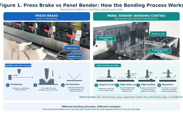
Figure 1. Fundamental forming principle: punch + V-die bending versus clamped sheet + controlled bending blades.
A press brake creates the bend through punch-and-die interaction.
A panel bender clamps the sheet and forms the flange using controlled blade movement.
This difference influences almost every other comparison:
· tooling;
· geometry;
· thickness range;
· handling;
· programming;
· and automation.
Neither principle is universally superior.
Press brakes generally provide a much wider thickness and force range.
Large hydraulic press brakes can be configured for:
· thin sheet;
· medium plate;
· thick plate;
· high-strength steel;
· large radii;
· and high-tonnage applications.
Panel benders are typically optimized for sheet-metal panel work, but their actual thickness capacity varies substantially between machine models.
For example, Salvagnini currently publishes P4 configurations capable of processing steel around the 3.2 mm class at specified material strength and angle conditions, while stainless and aluminium limits differ.
Prima Power’s BCe data similarly shows model-dependent capacities of approximately:
· 3.0–3.2 mm steel at 410 N/mm² UTS;
· 2.0–2.2 mm stainless steel;
· 4.0 mm aluminium.
ZYCO’s current C-series published specifications are more conservative, with model-dependent values around:
· 1.5 mm cold plate;
· 0.8–1.5 mm stainless steel;
· 2–3 mm aluminium.
These examples demonstrate why there is no useful universal statement such as:
"A panel bender can bend 3 mm steel."
A proper specification must include:
· machine model;
· material;
· tensile strength;
· bend length;
· angle;
· and geometry.
Press brakes are available across an extremely broad range of working lengths and tonnages.
Manufacturers such as LVD publish standard, robotic and XXL press brake platforms, including solutions for large and heavy parts.
Panel benders have a more defined part envelope.
The buyer must check:
· maximum blank length;
· maximum blank width;
· maximum bend length;
· maximum rotatable diagonal;
· minimum part dimensions;
· part weight;
· and manipulator limitations.
Prima Power’s BCe, for example, publishes specific values for maximum bending length, sheet dimensions and diagonal.
A panel may fit within nominal sheet dimensions but still fail because its diagonal cannot rotate inside the machine.
This is one of the most frequently overlooked panel-bender specifications.
A press brake buyer normally focuses on:
· daylight;
· stroke;
· throat depth;
· tooling height;
· and interference.
A panel-bender buyer must pay particular attention to:
maximum bend height
For example, current P4 configurations publish bend-height limits in the approximately 200–260 mm range for several standard models, while Prima Power BCe configurations publish approximately 204 or 264 mm depending on version.
TRUMPF’s current Series 7000 information shows that larger bend heights are possible on some systems, again demonstrating that this is highly model-dependent.
Therefore:
Thickness and sheet size alone do not determine panel-bender feasibility.
The part may fail because of a high flange or deep-box geometry.
Press brakes are especially strong when production includes:
· irregular components;
· structural brackets;
· thick plate;
· long profiles;
· small custom parts;
· special radii;
· deep boxes requiring gooseneck tooling;
· hems;
· unusual forming sequences;
· and jobs requiring dedicated tools.
Panel benders are especially strong when the part family consists of:
· multi-sided panels;
· doors;
· electrical enclosures;
· cabinets;
· trays;
· appliance panels;
· elevator panels;
· HVAC components;
· and other sheet-metal parts that benefit from repeated edge bending and automatic rotation.
The important word is part family.
One individual component may be technically possible on both machines, but the economics may differ completely across a production family.
Tool changes are a normal part of production flexibility.
Different jobs may require different:
· punches;
· dies;
· V openings;
· radii;
· hemming tools;
· and special tools.
Automatic tool changers can significantly reduce setup.
TRUMPF’s ToolMaster, for example, automatically sets tooling for new programs, which is particularly relevant in small-batch production.
Many modern panel benders reduce manual tooling changes through universal or automatically configured tooling.
Salvagnini explicitly describes its P4 universal tools as automatically adapting during production without manual retooling for the supported geometry range.
However:
"Panel benders never require tool changes" is not universally correct.
TRUMPF panel bending systems, for example, use automatic blank holder tool setup and optional auxiliary tools for specific geometries.
The correct comparison is:
Press brakes achieve flexibility through interchangeable tooling; panel benders often reduce manual tooling intervention through adaptive or automatic tooling.
Setup time is heavily application-dependent.
· retrieving tools;
· installing tools;
· aligning segments;
· changing V-die opening;
· configuring backgauge;
· loading programs;
· testing first parts;
· adjusting crowning;
· and correcting springback.
Automatic tool changing, offline programming and angle measurement can reduce this substantially.
· loading program;
· selecting blankholder configuration;
· automatic tool setup;
· defining manipulator sequence;
· checking auxiliary tooling;
· and part feasibility confirmation.
Because the machine can often configure tooling automatically, panel bending can be particularly effective in frequent-changeover production.
This is why modern panel benders should not be described as machines only for mass production.
Salvagnini explicitly promotes batch-one and kit production using automatic adaptation of its universal tools.
A claim such as:
"Panel benders are three times faster."
is not technically valid without a defined part and process.
A panel bender may achieve much shorter production time on a multi-sided panel because it eliminates:
· repeated manual rotation;
· repositioning;
· physical handling;
· and some tooling changes.
But a simple one-bend bracket may not gain the same advantage.
The correct metric is:
Total finished-part cycle time
not:
single-bend stroke time
When comparing machines, record:
· loading time;
· positioning time;
· bend time;
· rotation time;
· regripping time;
· tooling/setup time;
· unloading time;
· and changeover time.
Only then can productivity be compared correctly.
Neither machine category has a universal accuracy advantage.
· material thickness;
· tensile strength;
· grain direction;
· springback;
· V opening;
· tooling condition;
· Y1/Y2 synchronization;
· backgauge accuracy;
· crowning;
· and angle correction.
LVD’s Easy-Form Laser system, for example, is designed to measure and compensate for material variations during bending.
· blank accuracy;
· initial referencing;
· manipulator positioning;
· clamping;
· material variation;
· blade control;
· adaptive compensation;
· and geometry.
Salvagnini describes integrated adaptive systems that compensate for changes in material and production conditions.
Therefore:
Accuracy should be compared using representative-part FAT results—not isolated brochure numbers.
Panel bending can be attractive for:
· stainless-steel doors;
· painted panels;
· appliance covers;
· elevator components;
· facade panels;
· and other appearance-sensitive parts.
TRUMPF currently describes its panel bending process as suitable for low-mark or mark-free processing in supported applications.
However, no machine should be assumed to be universally mark-free.
Surface results depend on:
· material condition;
· dirt;
· protective film;
· tool condition;
· contact pressure;
· bend radius;
· and part movement.
Press brakes can also protect surfaces through:
· coated tools;
· bending film;
· larger tool radii;
· polished tooling;
· and process optimization.
The operator may need to:
· support the sheet;
· position the flange;
· rotate the part;
· flip the part;
· change tooling;
· identify bend sequence;
· and respond to springback.
This can require significant skill, especially on complex parts.
The machine assumes more of the:
· positioning;
· rotation;
· handling;
· sequencing;
· and repeatable movement.
Operator dependence is therefore often lower after the program and machine setup are validated.
However, labor does not disappear.
Skills move toward:
· programming;
· feasibility analysis;
· material flow;
· automation maintenance;
· and process engineering.
A common comparison mistake is to compare:
manual press brake
with
fully automatic panel bender.
That is not a fair technology comparison.
Modern press brakes can also use:
· automatic tool changers;
· robot loading;
· automatic unloading;
· angle measurement;
· offline programming;
· gripper changes;
· and flexible automated cells.
LVD’s RBS 40, for example, can combine several press brake types with robot handling and offline programming without machine-side robot teaching.
LVD’s larger RBS 80 extends robotic press brake automation to larger parts and longer profiles.
TRUMPF likewise offers fully automated press brake cells as well as panel bending systems.
The correct comparison is therefore:
Manual Press Brake vs Robotic Press Brake vs Panel Bender
not simply:
Manual vs Automatic.
|
Factor |
Manual Press Brake |
Robotic Press Brake |
Panel Bender |
|
Human part handling |
High |
Low |
Low |
|
Tooling flexibility |
Very high |
Very high |
More geometry-oriented |
|
Automatic rotation |
No |
Yes |
Usually integrated |
|
Special tooling freedom |
Excellent |
Excellent |
More limited |
|
Programming complexity |
Moderate |
Higher |
Integrated machine software |
|
Offline programming |
Available |
Important |
Common |
|
Batch flexibility |
Excellent |
Good when programming is efficient |
Excellent on modern automatic systems |
|
High-volume production |
Operator-limited |
Strong |
Strong for suitable panels |
|
Labor reduction |
Limited |
High |
High |
|
Thick plate capability |
Strong |
Strong within robot payload |
More limited |
|
Initial automation investment |
Low–medium |
High |
High |
|
Best application |
Broad general fabrication |
Repeatable robot-feasible parts |
Panel-oriented multi-bend parts |
A robotic press brake can close much of the labor gap while preserving the tooling flexibility of press braking.
But robotic feasibility introduces additional constraints:
· robot payload;
· gripper design;
· regripping;
· part sag;
· blank variation;
· collision clearance;
· and programming.
The correct automation strategy should therefore begin with the actual part family.
For material range, the press brake usually provides the broader application envelope.
A press brake can be built with much greater:
· force;
· working length;
· daylight;
· stroke;
· throat depth;
· and tooling capacity.
Panel-bender capability varies much more by architecture.
Current manufacturer data illustrates this clearly.
Published data for several P4 models includes:
· minimum thickness around 0.5 mm;
· steel up to approximately 3.2 mm at defined material strength and bend-angle conditions;
· stainless up to approximately 2.5 mm in some conditions;
· aluminium up to approximately 4 mm in some conditions.
Published values include:
· 3.0–3.2 mm steel;
· 2.0–2.2 mm stainless;
· 4.0 mm aluminium;
· minimum thickness 0.5 mm.
ZYCO’s current published values for its C-series vary by machine and include:
· 1.5 mm cold plate;
· stainless from approximately 0.8 to 1.5 mm depending on model;
· aluminium from approximately 2 to 3 mm depending on model.
These differences prove an important purchasing rule:
Never buy a panel bender from a generic "maximum thickness" statement.
Ask for a complete table containing:
· material grade;
· tensile strength;
· thickness;
· bend angle;
· bend length;
· bend height;
· inside radius;
· and any limitations on special bends.
A panel bender should normally be evaluated first when the factory produces many parts such as:
· electrical cabinet panels;
· cabinet doors;
· elevator panels;
· appliance housings;
· HVAC panels;
· trays;
· shelves;
· facade components;
· equipment covers;
· shallow and medium-depth boxes;
· and repetitive multi-edge sheet-metal parts.
The common characteristic is not simply "thin sheet."
It is:
Multiple bends around a panel where automatic part positioning and rotation remove a large amount of manual handling.
A useful feasibility review should ask:
· How many edges are bent?
· How often is the part rotated?
· Are positive and negative bends required?
· What is the highest flange?
· Is there a return bend?
· Can the part rotate inside the machine?
· Does the manipulator have enough gripping area?
· Is the blank shape regular enough?
· Is the surface sensitive?
· Can the complete part be unloaded automatically?
A press brake is often the better starting point for:
· thick plate;
· high-strength materials;
· structural brackets;
· long profiles;
· short heavy components;
· irregular blanks;
· custom radius work;
· small special parts;
· parts requiring unusual punches;
· complex deep boxes;
· one-off fabrication;
· and subcontracting where future part geometry is unpredictable.
The reason is not simply higher force.
It is the combination of:
force + tooling freedom + open-ended part variety
This is why general fabrication shops frequently retain a press brake even after adding panel bending automation.
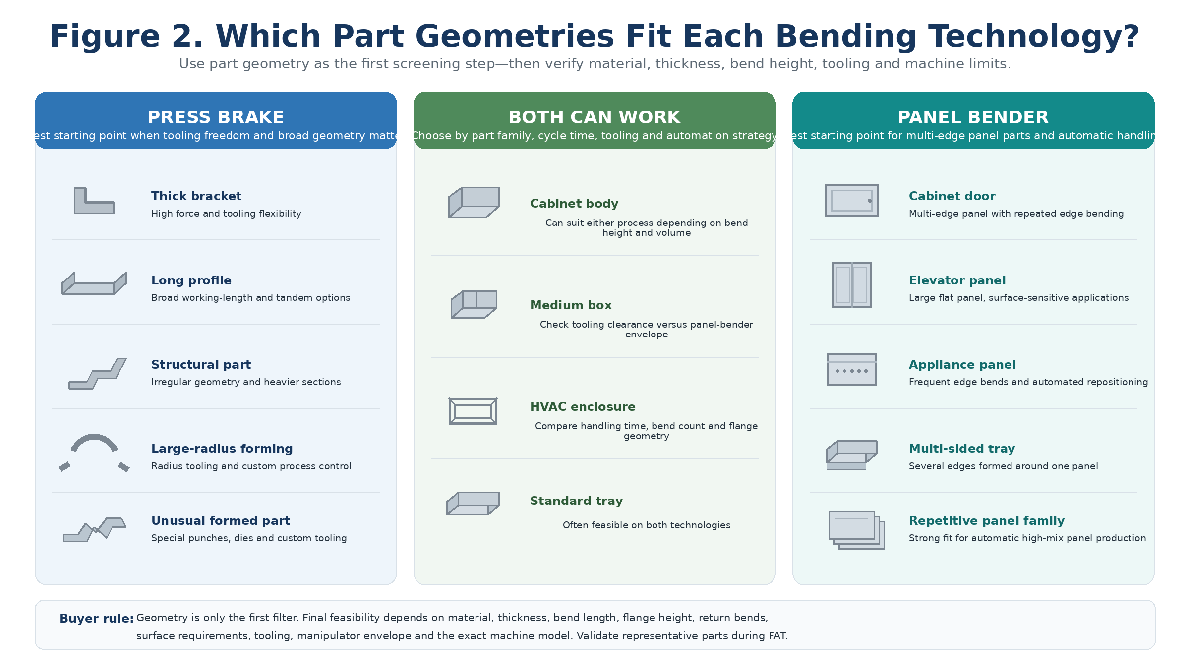
Figure 2. Typical part geometries that are better starting points for press brake, panel bender or both technologies.

Leave your email address and requirements, our professional sales team will develop the most suitable solution for you.


Copyright © 2026 Nanjing Zyco Cnc Machinery Co., Ltd. All Rights Reserved.
 Network Supported
 English
 français
 Deutsch
 italiano
 русский
 português
 español
 한국의
한국의 Türkçe
 العربية