
A Complete Guide to Tonnage, Bending Length, Stroke, Axes, Controllers and Tooling
Choosing the right press brake is not simply a matter of comparing machine tonnage, working length and price.
A press brake may have enough nominal tonnage but still be unsuitable because its working length is too short, its daylight is insufficient, its throat depth limits the part, its backgauge cannot position the required flanges, or its tooling cannot safely produce the target bend.
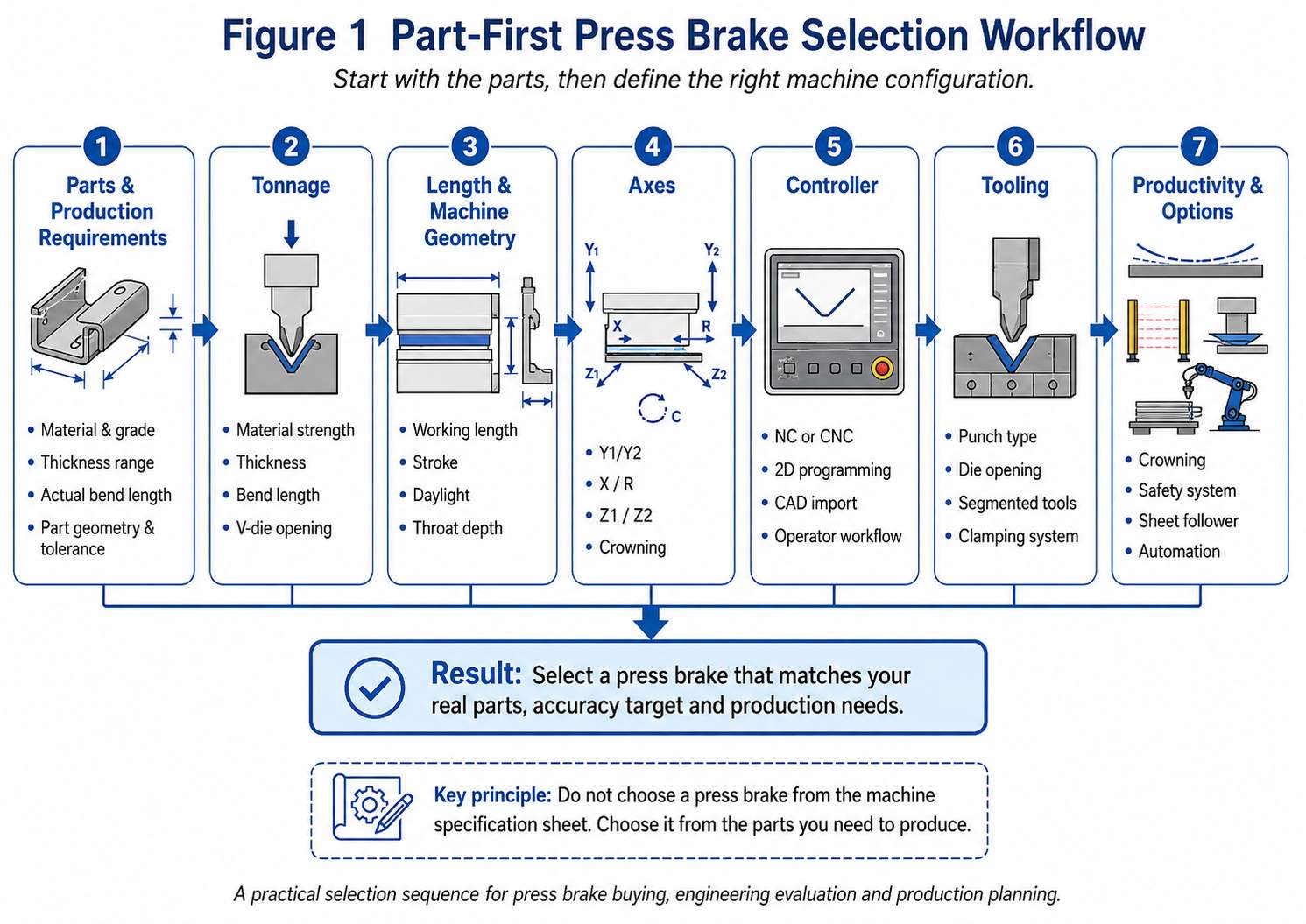
The most reliable selection process starts with the parts that must be produced.
Material type, sheet thickness, bend length, minimum flange, required inside radius, box depth, dimensional tolerance, batch size and product variety should be defined before deciding the machine configuration.
The correct selection sequence is:
Parts → Bending Force → Working Length and Machine Geometry → Axes → Controller → Tooling → Accuracy Options → Automation
This part-first method helps manufacturers avoid two common purchasing problems:
1. Buying a machine that cannot produce important parts.
2. Paying for functions that do not create practical production value.
The objective is not to purchase the press brake with the largest specification or the highest number of axes. The objective is to select a complete bending system that can produce the required parts safely, accurately and efficiently.
Do not choose a press brake from the machine specification sheet. Choose it from the parts you need to produce.
A specification sheet describes the capacity and configuration of a machine.
It does not automatically confirm whether the machine can produce a specific component.
A complete press brake evaluation must consider the interaction between:
· Material strength
· Sheet thickness
· Actual bend length
· Required inside radius
· Minimum flange
· Part depth
· Tooling height
· Bending method
· Backgauge configuration
· Deflection compensation
· Operator workflow
· Production volume
A machine should therefore be evaluated as part of a forming system rather than as an isolated piece of equipment.
Before requesting quotations, create a representative part list.
Do not evaluate the machine only from the largest sheet used in the factory. The most difficult part may instead be:
· A short but very thick plate
· A deep electrical cabinet
· A component with a narrow flange
· A tapered part
· A part requiring several different backgauge positions
· A long component with strict straightness requirements
· A high-strength steel component
· A product requiring a large inside radius
· A component with return flanges that can collide with the punch
The largest blank is not always the most demanding component.
A short, thick workpiece may create a high concentrated load. A deep box may require more stroke and daylight. A narrow flange may require a smaller V-opening. A complex multi-bend part may require additional backgauge axes and graphical programming.
The following information should be collected before machine selection.
| Production Information | Why It Matters | ||
| Material type and grade |
|
||
| Minimum and maximum thickness | Influences tonnage, V-opening and tool capacity | ||
| Maximum actual bend length | Determines the required working length | ||
| Maximum blank dimensions | Influences material handling and machine access | ||
| Minimum flange length | Limits the usable V-die opening | ||
| Required inside radius |
|
||
| Deepest box or channel |
|
||
| Part geometry |
|
||
|
|
||
|
|
||
|
|
||
|
|
||
|
|
||
|
|
Ideally, the part database should include drawings or 3D models rather than only a verbal description.
A machine supplier can evaluate the application much more accurately when the buyer provides actual part geometry.
A factory may produce hundreds of different components, but machine selection should focus on the parts that define the upper limits of the application.
Create separate groups for:
· Maximum thickness
· Maximum bend length
· Minimum flange
· Deepest box
· Smallest required radius
· Highest-strength material
· Most complex bending sequence
· Tightest angle tolerance
· Tightest flange-position tolerance
· Highest annual production volume
These requirements may come from different parts.
For example, one component may determine the required tonnage, while another determines the required daylight and a third determines the backgauge configuration.
That is why selecting a press brake from only one sample part can produce an incomplete result.
Future production should be considered, but it should not become an excuse for uncontrolled over-specification.
Separate requirements into three categories:
Parts currently being manufactured or already ordered.
Parts supported by clear business opportunities, customer programs or production plans.
Parts that may theoretically be produced but have no defined commercial requirement.
The machine should fully support confirmed production and reasonably support probable future production.
It is normally not economical to purchase excessive tonnage, length, axes and automation only for undefined possibilities.
Different press brake structures are suitable for different production requirements.
The machine type should be selected before comparing detailed configurations.
A torsion-bar synchronized press brake mechanically connects the left and right sides of the ram through a torsion shaft.
It is generally suitable for:
· Simple bending work
· Relatively stable material thickness
· Moderate accuracy requirements
· Repetitive parts
· Limited production variety
· Budget-sensitive applications
Its advantages are usually a simpler structure, lower initial investment and straightforward operation.
However, it normally offers less flexibility in ram synchronization, compensation and multi-axis configuration than an electro-hydraulic CNC press brake.
It should not be selected only because it is less expensive. The buyer should first confirm that its accuracy and programming capability match the actual parts.
An electro-hydraulic synchronous press brake controls the left and right ram positions independently through Y1 and Y2 axes.
It is widely used for:
· High-mix sheet metal production
· Complex bending
· Higher angle consistency
· Multi-axis backgauges
· Graphical CNC programming
· Long-part bending
· CNC crowning systems
· Automated bending applications
This configuration offers greater control over ram parallelism, programming and production flexibility.
For factories producing different materials, thicknesses and part geometries, an electro-hydraulic CNC press brake is often the more adaptable long-term solution.
A servo-electric press brake uses an electric drive system rather than a conventional hydraulic system.
It is commonly considered for:
· Thin and medium-gauge sheet metal
· Shorter working lengths
· High-cycle production
· Clean production environments
· Applications prioritizing energy efficiency
· Precision components with frequent program changes
Its suitability depends on the required tonnage, working length, local service capability and production mix.
Servo-electric machines should be evaluated from the complete production requirement, not only from energy-consumption claims.
A tandem system combines two press brakes to bend very long components.
It may be appropriate for:
· Poles
· Long structural components
· Large panels
· Transportation equipment
· Shipbuilding components
· Long architectural products
The machines may operate together or separately, depending on the design.
Tandem applications require careful evaluation of synchronization, foundation, tooling alignment, material handling and operator safety.
A compact heavy-plate press may be more practical when the factory mainly bends short and thick components.
For example, a company producing carbon steel parts shorter than approximately 800 mm but up to approximately 20 mm thick may not benefit from purchasing a conventional long-bed press brake only to obtain the required tonnage.
A compact heavy-duty structure can provide several potential advantages:
· Smaller floor-space requirement
· Better suitability for concentrated heavy bending
· Shorter material-handling distance
· Reduced unnecessary bed length
· More focused investment for the target application
The final decision must still consider tooling load, frame design, actual bend length, material strength and required production rate.
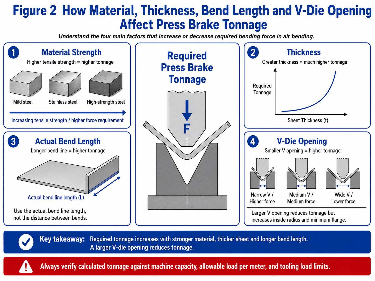
Press brake tonnage determines whether the machine can generate sufficient force for the required bend.
However, tonnage should never be selected from thickness alone.
For air bending, the required force is mainly influenced by:
· Material tensile strength
· Sheet thickness
· Actual bend length
· V-die opening
· Bending method
· Tooling geometry
· Required radius
A simplified relationship can be expressed as:
Bending force increases with material strength, bend length and the square of sheet thickness, while a larger V-die opening reduces the required force.
This relationship explains why small changes in thickness can produce a substantial increase in tonnage.
Carbon steel is commonly used as the reference material in press brake tonnage charts.
Materials with higher tensile strength generally require more bending force.
For example:
· Stainless steel usually requires more force than ordinary mild steel.
· High-strength steel may require significantly more force.
· Aluminum commonly requires less force than mild steel, depending on alloy and temper.
The material name alone is not always sufficient.
“Stainless steel,” “aluminum” and “high-strength steel” each contain many grades with different mechanical properties.
For critical applications, the actual material grade and tensile-strength range should be used.
Bending force increases approximately with the square of sheet thickness in common air-bending calculations.
This means doubling the thickness can require much more than twice the force.
A machine that comfortably bends 3 mm material may not be suitable for 6 mm material at the same bend length and V-opening.
Thickness variation also affects:
· Required V-opening
· Inside radius
· Minimum flange
· Tool load
· Angle consistency
The buyer should provide both the nominal thickness and the realistic production tolerance.
Tonnage should be calculated using the actual bend-line length, not automatically the full sheet width.
A 3,000 mm-wide blank may contain a bend that is only 800 mm long.
Conversely, several smaller parts may be bent simultaneously across a longer section of the bed.
The machine requirement should therefore reflect the true loaded length.
The V-die opening has a direct effect on bending force.
A smaller opening generally:
· Increases required tonnage
· Produces a smaller air-bent inside radius
· Supports a shorter flange
· Increases local tool pressure
· Increases the risk of marking or cracking certain materials
A larger opening generally:
· Reduces required tonnage
· Produces a larger inside radius
· Requires a longer minimum flange
· May reduce the ability to produce small features
The V-opening cannot therefore be selected only to reduce machine tonnage.
It must also satisfy the required radius and minimum flange.
Use the ZYCO V-die selection resources to compare thickness, opening, inside radius and minimum flange before finalizing the machine capacity.
Recommended Internal Links:
· Press Brake V-Die Selection Chart
https://calculator.zycomachine.com/engineering-tools/press-brake-v-die-selection-chart
· How to Choose the Correct Press Brake V-Die Opening
https://calculator.zycomachine.com/engineering-tools/how-to-choose-press-brake-v-die-opening
· Minimum Flange Length Guide
https://calculator.zycomachine.com/engineering-tools/minimum-flange-length-guide
Air bending, bottoming and coining require different force levels.
Air bending normally uses the lowest force and offers the greatest flexibility because one tooling set can produce different angles through ram-depth control.
Bottoming requires more force and depends more strongly on tool angle and material behavior.
Coining requires substantially higher force and is not appropriate for every machine or tooling system.
The machine must be selected for the actual forming method rather than assuming every published tonnage chart applies to every process.
A machine rated for a certain total tonnage does not automatically allow the full force to be concentrated over a very short section of the bed.
The buyer must confirm:
· Maximum total machine force
· Allowable force per meter
· Minimum permitted loaded length
· Off-center loading restrictions
· Upper-tool load rating
· Lower-tool load rating
· Tool-holder load rating
· Table and ram load limits
This is especially important for short and thick parts.
A machine may have sufficient total tonnage but still exceed the permitted local load of the tooling or frame.
A production machine should not be selected so that normal parts require the absolute rated capacity under ideal assumptions.
Real production includes:
· Material-strength variation
· Thickness variation
· Tool wear
· Different V-openings
· Setup variation
· Future product changes
A reasonable operating reserve helps prevent continuous operation at the machine’s maximum limit.
However, excessive reserve increases machine cost, size, power requirement and tooling cost.
The reserve should be selected from actual production uncertainty and confirmed with the machine and tooling supplier.
A press brake tonnage calculator is useful for preliminary selection, but the result should be verified against:
· Material data
· Tooling load limits
· Machine load-distribution rules
· Actual bending method
· Part geometry
· Production trials where possible
Recommended Internal Links:
· Press Brake Tonnage Calculator
https://calculator.zycomachine.com/engineering-tools/press-brake-calculator
· Press Brake Tonnage Guide
https://calculator.zycomachine.com/engineering-tools/press-brake-tonnage-guide
The working length should be based on the maximum actual bend that the factory must produce.
Do not automatically select the machine from the maximum sheet dimension.
A blank may be wider than the bend line.
For example, a large sheet may contain:
· A short partial bend
· Several separate bends
· A bend positioned at an angle
· A return flange that interacts with the side frame
The buyer should evaluate the bend geometry rather than using only the blank size.
The published working length is not the same as the distance between the machine side frames.
A part may fit across the tooling but still interfere with the frame during positioning or rotation.
This issue is especially important for:
· Deep boxes
· Large panels
· Parts with side flanges
· Components requiring multiple rotations
· Off-center bends
The part should be checked through the complete bending sequence.
A longer machine is not automatically a better machine.
Increasing bed length may increase:
· Purchase price
· Machine footprint
· Foundation requirements
· Deflection-control requirements
· Tooling investment
· Material-handling distance
· Transportation and installation cost
If the factory mainly produces short parts, an unnecessarily long machine may reduce rather than improve efficiency.
Some factories place several identical small components across the bed and bend them in one cycle.
This can increase productivity, but the evaluation must include:
· Total loaded length
· Equal part positioning
· Tool segmentation
· Load distribution
· Operator safety
· Part removal
· Variation between positions
Multiple-part bending should be planned deliberately rather than assumed from the nominal working length.
Future production expansion may justify additional working length.
However, the buyer should compare two alternatives:
1. Purchasing a longer machine now.
2. Outsourcing or purchasing a dedicated machine later if long parts become a regular product.
The most economical choice depends on the probability, volume and value of future work.
Tonnage and working length receive most of the attention during press brake purchasing.
Machine geometry is often overlooked.
A press brake may have enough force and length but still be unable to produce the part because the available working space is insufficient.
Stroke is the maximum travel distance of the ram.
More stroke may be required for:
· Tall tooling
· Deep boxes
· Large-radius tooling
· Special forming tools
· Parts requiring additional insertion clearance
· Components that must be removed at an angle
Stroke should not be evaluated independently.
The actual usable opening also depends on daylight, tooling height and the programmed upper position.
Daylight is the vertical distance available between the ram and table when the ram is at its upper position.
Manufacturers may define the measurement differently, so the buyer should confirm whether the published value is measured:
· Without tooling
· Between tool holders
· From ram to table
· At a specific ram position
Sufficient daylight is important for:
· Deep channels
· Tall punches
· Large-radius tools
· Hemming systems
· Special forming operations
· Easy part insertion and removal
A large nominal daylight does not guarantee sufficient usable space after tooling is installed.
Throat depth is the distance from the bending centerline to the inner side of the machine frame.
It determines how far a large sheet can enter the machine around the side-frame area.
Throat depth matters when:
· The bend line is far from the edge of the sheet.
· A large panel must pass between the frames.
· A previous flange changes the part’s orientation.
· The workpiece must rotate during a multi-bend sequence.
For many ordinary parts, standard throat depth is adequate.
For large panels and specialized products, it can become a decisive limitation.
The distance between frames affects whether a component can be inserted, rotated and removed.
A machine may advertise a 3,200 mm working length, but the distance between frames will be shorter.
When a component has large side flanges or a deep body, this difference can affect manufacturability.
The total installed tool height includes:
· Upper tool holder
· Punch
· Lower tool holder
· Die
· Adapters
· Quick-clamping components
· Special tooling
The machine supplier should evaluate the proposed tooling stack together with stroke and daylight.
This is particularly important for:
· Gooseneck punches
· Tall punches
· Large V-dies
· Adjustable dies
· Hemming tools
· Radius tooling
· Custom forming tools
Table height influences:
· Operator posture
· Material support
· Compatibility with front support arms
· Integration with conveyors or robots
· Handling of large panels
A machine should not be evaluated only from forming capacity.
Poor ergonomics can reduce productivity and increase operator fatigue even when the machine is technically capable.
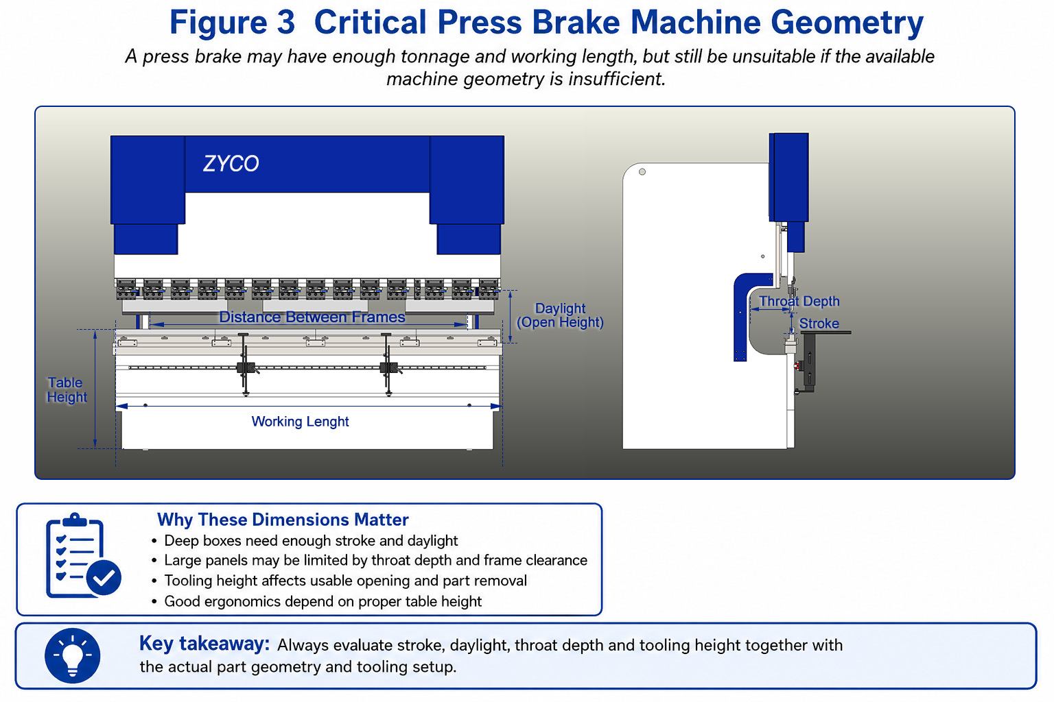
Diagram Labels:
· Working length
· Distance between frames
· Stroke
· Daylight
· Throat depth
· Table height
Recommended Alt Text:
Press brake geometry diagram identifying working length, stroke, daylight, throat depth, frame distance and tooling height.
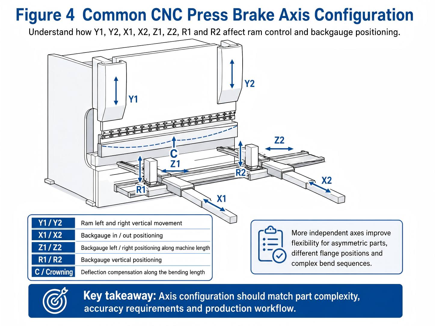
Axis selection should be based on part geometry and positioning requirements.
More axes do not automatically make a press brake more accurate or more productive.
An axis creates value only when the production process can use it.
Y1 and Y2 independently control the left and right sides of the ram on an electro-hydraulic synchronous press brake.
They support:
· Ram synchronization
· Position correction
· Controlled tilt where permitted
· Higher bending consistency
· Integration with CNC crowning and angle-control strategies
Y1/Y2 control is one of the main differences between electro-hydraulic synchronous and torsion-bar machines.
The X axis controls the front-to-back position of the backgauge.
It determines the flange dimension for many standard bends.
A basic X axis may be sufficient for:
· Rectangular parts
· Repetitive flange dimensions
· Simple brackets
· Low-complexity production
The required travel and speed should be checked against the actual flange range.
The R axis moves the backgauge fingers vertically.
It is useful when:
· The part has different step heights.
· A previous bend changes the support level.
· The workpiece must be gauged above or below the normal position.
· Complex bend sequences require different finger heights.
R-axis control can reduce manual adjustment and improve setup consistency.
Z1 and Z2 move the backgauge fingers independently along the working length.
They are useful for:
· Parts of different widths
· Off-center components
· Asymmetrical parts
· Multiple parts placed across the machine
· Frequent product changes
Independent Z-axis movement can reduce manual finger positioning.
Independent X1 and X2 control allows the left and right backgauge fingers to use different front-to-back positions.
It may be required for:
· Tapered parts
· Angled bends
· Asymmetrical flange positions
· Specialized components
This function should be selected only when the actual part geometry requires independent depth positioning.
Independent R1 and R2 control allows different vertical positions for the left and right fingers.
It is used for specialized asymmetrical or complex gauging applications.
For many factories, a common R axis is sufficient.
A CNC crowning system adjusts the table-compensation profile according to the expected deflection.
It may be treated as an additional controlled axis in machine specifications.
The purpose is not to position the workpiece but to improve angle consistency across the bending length.
Additional controlled functions may include:
· Sheet followers
· Front supports
· Robotic interfaces
· Automatic tool changers
· Angle-measuring systems
· Material-handling systems
These systems should be evaluated as part of the production cell.
|
|
||
|
Basic ram control and X-axis positioning | ||
|
Y1/Y2, X, R and CNC crowning | ||
|
Add Z1/Z2 | ||
|
Consider X1/X2 | ||
|
Multi-axis backgauge with graphical CNC | ||
| Production Requirement | Practical Axis Configuration | ||
| Automated bending cell |
|
The ideal configuration is not the machine with the most axes.
It is the machine with the axes that eliminate real setup, positioning and production problems.
The controller should be selected after the mechanical configuration has been defined.
Choosing the controller first can lead to paying for software functions that the machine cannot use or selecting a controller that does not support the required axes.
The selection should consider:
· Number of controlled axes
· Programming method
· Part complexity
· Operator experience
· Product variety
· Offline programming requirements
· CAD-data availability
· Automation requirements
· Service and language support
A numerical NC controller is generally suitable for:
· Simple parts
· Repetitive production
· Basic ram and backgauge positioning
· Operators who already understand bend sequencing
· Applications with limited product variety
It may provide efficient control for straightforward work without the cost and complexity of advanced graphical programming.
A CNC controller provides greater control over:
· Multiple axes
· Program storage
· Material libraries
· Tool libraries
· Correction values
· Repeated production
It is suitable for factories that require more flexibility and repeatability.
A 2D graphical controller allows the operator to draw or import the part profile and generate bending steps more visually.
It is useful for:
· Electrical enclosures
· Cabinets
· Brackets
· Channels
· High-mix sheet metal work
· Operators who benefit from visual programming
Important functions may include:
· Profile drawing
· Automatic bend sequencing
· Tool selection support
· Collision warnings
· Bend simulation
· Program correction
CAD import can reduce manual programming when the factory already has digital part files.
The buyer should confirm:
· Supported file formats
· Whether the controller imports profiles or complete 3D models
· Whether geometry requires cleanup
· Whether additional software licensing is required
· Whether offline programming is included
“CAD import” can describe different functions on different controllers.
It should be demonstrated using the buyer’s actual file format.
Advanced controllers may provide 2D or 3D visualization and machine simulation.
These functions can help:
· Identify collisions
· Review bend sequence
· Check part orientation
· Train operators
· Reduce trial-and-error setup
However, visualization does not eliminate the need to confirm actual tooling, machine geometry and material behavior.
Offline programming can reduce machine idle time by allowing programs to be prepared away from the press brake.
It is most valuable when:
· Product variety is high.
· Programming time is significant.
· Several machines share programs.
· Production planning is centralized.
· The factory uses CAD/CAM workflows.
For low-volume simple work, offline software may not provide the same return on investment.
Select the controller that matches the machine axes, operator workflow and part complexity—not the controller with the longest feature list.
For a complete comparison of EASYCAT, Delem, Cybelec and ESA control options, refer to:
Press Brake Controller Selection Guide
https://calculator.zycomachine.com/engineering-tools/press-brake-controller-selection-guide
The press brake and the tooling form one bending system.
Tooling should not be treated as a minor accessory selected after the machine order.
The tooling determines:
· Bend angle
· Inside radius
· Minimum flange
· Maximum safe load
· Collision clearance
· Surface marking
· Setup time
· Part flexibility
Suitable for many open-profile bends and general fabrication.
Provides clearance for return flanges, boxes and channels.
The gooseneck depth must be matched to the part geometry.
Used for acute-angle bending and some hemming processes.
It requires careful force and tooling-load evaluation.
Used when the part requires a larger inside radius than standard air bending would naturally produce.
Used for channels, offsets, beads, hinges or custom profiles.
Special tooling may require additional stroke, daylight and tonnage.
Provides one fixed V-opening and is often selected for a defined thickness range.
Provides several V-openings in one die body.
It offers flexibility but may be heavier and less convenient to rotate.
Allows the opening to be adjusted for different plate thicknesses and radii.
It is often used for heavy plate applications.
Used for pre-hemming and final hemming operations.
The machine and tool must be evaluated for the required closing force.
Segmented tooling allows the operator to configure different lengths and create clearance for box and panel bending.
It is important for:
· Cabinets
· Electrical enclosures
· Boxes
· Short parts
· Mixed production
· Return flanges
The segment lengths should match the factory’s typical products.
Every component in the tooling system has a load limit:
· Punch
· Die
· Upper holder
· Lower holder
· Adapter
· Clamping system
The lowest-rated component determines the safe tooling capacity.
A high-tonnage machine does not make low-capacity tooling safe.
Short, thick bends require particular attention because the load is concentrated over a small tool length.
Suitable for infrequent tooling changes and budget-sensitive applications.
Reduces setup time and improves tool alignment compared with conventional manual fastening.
Suitable for frequent tool changes, high-mix production and advanced automation.
The value of quick clamping depends on how often tools are changed.
The buyer should confirm:
· Tooling standard
· Tang type
· Tool-holder compatibility
· Safety-groove design
· Segmentation
· Existing tool compatibility
· Future local availability
A machine with a non-standard or poorly supported tooling interface can create long-term cost and supply problems.
The press brake and tooling should be selected as one forming system, not as two independent purchases.
Recommended Internal Link:
Press Brake Tooling Selection Guide
https://calculator.zycomachine.com/engineering-tools/press-brake-tooling-selection-guide
When a long part is bent, the ram and table can deflect under load.
This can create an angle difference between the center and ends of the workpiece.
Crowning compensates for this expected deflection.
A manual mechanical crowning system uses adjustable wedges or a mechanical compensation mechanism.
It can be suitable for:
· Stable product ranges
· Repetitive material and thickness
· Applications where frequent automatic adjustment is unnecessary
It requires the operator to set the compensation value.
CNC mechanical crowning uses a motorized wedge system controlled by the CNC.
It can adjust compensation according to programmed conditions.
Advantages may include:
· Faster setup
· Better repeatability
· Easier program storage
· Greater suitability for mixed production
During a long bend, load causes the ram and bed to deflect in opposite directions. The center of the tooling then penetrates the sheet less than the ends, commonly leaving the middle angle more open. Crowning introduces a controlled counter-curve or support force in the lower beam so effective penetration remains uniform along the bending length.
Crowning primarily addresses deflection along the working length.
It cannot independently correct:
· Inconsistent material thickness
· Variable tensile strength
· Incorrect V-opening
· Worn tooling
· Poor tool alignment
· Incorrect bend deduction
· Backgauge errors
· Local part deformation
· Operator handling variation
Accurate bending requires the complete system to be controlled.
Important factors include:
· Machine-frame rigidity
· Ram synchronization
· Backgauge positioning accuracy
· Tool alignment
· Tool wear
· Material consistency
· Temperature
· Springback
· Bend-sequence planning
· Operator measurement method
A machine specification alone does not guarantee final part accuracy.
Some press brakes use automatic angle-measurement or correction systems.
These systems may reduce first-piece adjustment and compensate for material variation.
Their value is highest when:
· Angle tolerance is strict.
· Material varies between batches.
· Production volume justifies the investment.
· Setup reduction is commercially important.
They should be tested with representative materials and part geometry.
Recommended Internal Link:
Press Brake Crowning Guide
https://calculator.zycomachine.com/engineering-tools/press-brake-crowning-guide
Automation should solve a defined production problem.
It should not be selected only because it appears advanced.
Front support arms help support large or heavy sheets.
They improve handling but still require operator coordination.
Sheet followers support the workpiece as it rotates during bending.
They can reduce:
· Operator effort
· Part scratching
· Handling variation
· Risk of uncontrolled plate movement
They are especially useful for large panels.
A modern press brake should include a safety solution appropriate to local regulations and the production process.
The system should protect the operator while minimizing unnecessary interruption of the bending cycle.
Safety configuration must be evaluated together with:
· Tool geometry
· Closing speed
· Part shape
· Operator position
· Local compliance requirements
Automatic tool changing can provide value in high-mix production where tooling setup is a major bottleneck.
It requires:
· Standardized tooling
· Tool-storage planning
· Accurate program management
· Sufficient production volume
· Suitable part families
It is not automatically economical for low-volume simple production.
Robotic bending may be appropriate for:
· Repetitive parts
· Stable material dimensions
· High production volume
· Labor-intensive handling
· Consistent part presentation
· Controlled production environments
Complex high-mix parts can also be automated, but programming, gripper design and changeover become more demanding.
Automation should remove a clearly identified production bottleneck.
Before purchasing an option, define:
· Current setup time
· Current cycle time
· Labor requirement
· Quality losses
· Downtime source
· Expected production increase
· Expected payback
The lowest machine price does not always create the lowest production cost.
A complete comparison should include:
· Machine purchase price
· Tooling
· Transportation
· Installation
· Foundation
· Commissioning
· Training
· Power consumption
· Hydraulic oil
· Filters and seals
· Software licensing
· Spare parts
· Maintenance labor
· Service response
· Production downtime
· Operator skill requirement
· Resale value
· Future expansion
A machine quotation may include only a basic punch and die.
The factory may still require:
· Segmented tools
· Gooseneck punches
· Additional V-openings
· Radius tools
· Hemming tools
· Special forming tools
· Tool cabinets
· Quick clamping
Tooling cost should be evaluated at the same time as the machine.
An advanced controller can reduce setup time, but operators must be trained to use it.
The buyer should confirm:
· Training language
· Training duration
· Programming support
· Manuals
· Video resources
· Remote support
· Post-installation assistance
Important questions include:
· Which parts are stocked locally?
· Which components are standard international brands?
· How quickly can remote diagnosis begin?
· Is electrical documentation supplied?
· Are hydraulic and mechanical drawings included?
· What is the warranty process?
· Are software updates available?
A low-cost machine can become expensive if a minor failure causes prolonged downtime.
The buyer should confirm whether the quoted controller price includes:
· Offline programming
· CAD import
· Network connectivity
· Additional language packages
· Software updates
· Remote support functions
Do not assume every displayed software feature is included in the standard quotation.
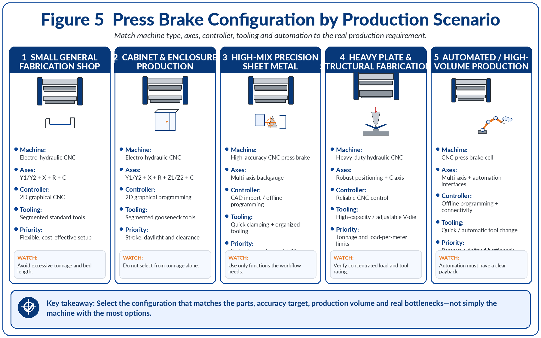
The following configurations are examples of selection logic, not universal machine specifications.
Final selection should be based on actual part drawings and calculations.
· Mild steel and stainless steel
· Low to medium batch sizes
· Brackets, frames and general components
· Frequent product changes
· Moderate accuracy requirements
· Electro-hydraulic CNC press brake for greater flexibility
· Working length based on the longest confirmed bend
· Y1/Y2, X, R and crowning
· 2D graphical programming where product variety is high
· Segmented standard punches
· Several commonly used V-openings
· Mechanical quick clamping
Purchasing excessive working length and tonnage while underinvesting in tooling and programming convenience.
· Thin and medium-gauge sheet
· Carbon steel, galvanized steel and stainless steel
· Deep boxes
· Return flanges
· High product variety
· Tight dimensional requirements
· Electro-hydraulic CNC press brake
· Adequate daylight and stroke
· Y1/Y2, X, R, Z1/Z2 and crowning
· 2D graphical CNC with bend-sequence assistance
· Segmented gooseneck tooling
· Quick clamping
· Sheet-support options where panels are large
Selecting the machine from tonnage alone and discovering that tooling clearance or daylight is insufficient.
· Frequent new products
· Short production runs
· Strict angle and flange tolerances
· Multiple materials
· Complex bending sequences
· High-accuracy electro-hydraulic CNC press brake
· Multi-axis backgauge
· Graphical controller
· CAD import or offline programming
· CNC crowning
· Fast tool-change system
· Optional angle measurement
· Organized segmented-tooling system
Buying many axes and software functions without developing standardized tooling, programming and setup procedures.
· Thick carbon steel
· High-strength plate
· Structural brackets
· Heavy components
· Lower product variety
· High local forming loads
· Heavy-duty hydraulic CNC press brake
· Tonnage verified for material strength and V-opening
· Machine and tooling force-per-meter limits confirmed
· Large-capacity punch and die system
· Adjustable or large-opening V-dies where appropriate
· Strong front supports or lifting equipment
· Machine geometry matched to large tooling
Confirming only total machine tonnage while ignoring concentrated load and tooling capacity.
· Long panels
· Poles
· Large structural parts
· Transportation components
· Architectural products
· Long-bed or tandem press brake
· Controlled ram synchronization
· CNC crowning
· Material-support system
· Tool alignment plan
· Foundation and floor-space evaluation
· Detailed handling and safety procedure
Underestimating deflection, handling difficulty, installation requirements and frame interference.
· Carbon steel components
· Short bend lengths
· High thickness
· Concentrated production load
· Heavy parts with limited width
· Compact heavy-duty bending press or appropriately designed short-bed press brake
· Tooling and frame verified for concentrated load
· Large-opening heavy-duty dies
· Simple but robust positioning system
· Suitable lifting and handling equipment
· Machine footprint matched to the production area
Purchasing a conventional long machine only to obtain tonnage while paying for bed length that is not used.
A manufacturer produces electrical cabinets from:
· 1.5–3 mm mild steel
· Galvanized steel
· Stainless steel
· Multiple box depths
· Frequent product changes
· Medium batch quantities
The maximum material thickness does not require extreme tonnage.
The more important factors are:
· Return-flange clearance
· Deep-box geometry
· Frequent programming
· Different flange positions
· Angle consistency
· Setup time
· Electro-hydraulic synchronous CNC press brake
· Working length matched to the largest panel bend
· Adequate stroke and daylight
· Y1/Y2, X, R, Z1/Z2 and crowning
· 2D graphical controller
· Segmented gooseneck punches
· Multiple V-openings
· Quick clamping
For this factory, tooling clearance, programming efficiency and backgauge flexibility are more important than purchasing unnecessarily high tonnage.
A company produces brackets and structural components from:
· 6–10 mm carbon steel
· Medium bend lengths
· Moderate product variety
· Relatively large inside radii
· Heavy workpieces
The main requirements are:
· Sufficient tonnage
· Correct V-die opening
· Tool-load capacity
· Machine rigidity
· Material handling
· Local load verification
· Heavy-duty hydraulic CNC press brake
· Tonnage calculated from actual grade, thickness, bend length and V-opening
· Large-capacity tooling
· Adjustable or multiple heavy-duty dies
· Strong front supports
· CNC crowning for long bends
· Simple and reliable backgauge configuration
The machine must be selected as a load-bearing system.
Machine tonnage, force per meter, punch capacity, die capacity and clamping capacity must all be verified.
A manufacturer needs to bend carbon steel parts with:
· Maximum thickness of approximately 20 mm
· Bend lengths below approximately 800 mm
· Relatively low product variety
· High local forming force
· Limited workshop space
A conventional long-bed press brake may provide the required tonnage, but much of the working length would remain unused.
The application is defined more by concentrated heavy bending than by long-sheet production.
· Compact heavy-duty press
· Short, rigid working structure
· Tooling verified for high local load
· Appropriate large V-opening
· Strong material supports
· Simple positioning system
· Safe lifting and handling process
The correct machine is not always the largest conventional press brake.
A specialized machine can provide a better match between investment, floor space and actual production.
A lower price may exclude important tooling, axes, safety systems, installation, software or service.
Compare the complete production solution.
Tonnage also depends on material strength, bend length, V-opening and bending method.
A smaller V-opening can significantly increase force and change the inside radius and minimum flange.
Short, thick parts may exceed local machine or tooling limits even when total machine tonnage appears sufficient.
Unused working length increases cost, floor-space requirement and tooling investment.
The machine may have enough force but insufficient working space for deep parts or tall tooling.
Unused axes increase cost and complexity without improving productivity.
The controller should support the selected mechanical axes and workflow.
The mechanical configuration must be defined first.
Tooling determines whether the part can actually be formed.
The machine and tooling must be selected together.
A machine creates value only when it can remain in production and operators can use it effectively.
Use the following checklist when requesting a quotation.
· Material types
· Exact material grades
· Minimum thickness
· Maximum thickness
· Maximum actual bend length
· Maximum blank dimensions
· Required inside radius
· Maximum box depth
· Most complex part drawing
· Tightest angle tolerance
· Tightest flange-position tolerance
· Annual production volume
· Typical batch size
· Required tonnage
· Required force per meter
· Required working length
· Distance between frames
· Throat depth
· Stroke
· Daylight
· Table height
· Off-center loading requirement
· Concentrated-load requirement
· Y1/Y2
· X
· R
· Z1/Z2
· X1/X2
· R1/R2
· Crowning axis
· Sheet follower
· Angle measurement
· Robotic or automation interface
· Numerical or graphical programming
· 2D profile drawing
· CAD import
· Automatic bend sequencing
· Collision checking
· Tool library
· Material library
· Offline programming
· Network connection
· Required interface languages
· Tooling standard
· Straight punches
· Gooseneck punches
· Radius punches
· Acute punches
· Segmented tooling
· Required V-openings
· Adjustable V-die
· Hemming tooling
· Special forming tools
· Tool load ratings
· Manual, mechanical or hydraulic clamping
· Machine synchronization
· Mechanical or hydraulic crowning
· Backgauge positioning accuracy
· Angle-measurement requirement
· Tool alignment method
· First-piece correction process
· Safety system
· Front support arms
· Sheet followers
· Quick clamping
· Tool storage
· Automatic tool changing
· Robot compatibility
· Material-handling equipment
· Included tooling
· Installation
· Commissioning
· Training
· Warranty
· Spare-parts package
· Electrical documentation
· Hydraulic documentation
· Software licenses
· Remote support
· Local service
· Delivery time
· Foundation requirements
· Machine voltage
· Compliance documentation
A reliable press brake purchasing process can be summarized in seven steps.
Collect representative drawings and identify the parts that define the maximum requirements.
Use the actual material grade, thickness, bend length and V-die opening.
Confirm working length, frame distance, stroke, daylight, throat depth and tooling height.
Choose the backgauge and compensation axes required by the actual part geometry.
Match the controller to the selected axes, operator skills and programming workflow.
Confirm punch geometry, die openings, segmentation, load capacity and clamping.
Compare the complete production solution rather than only the machine purchase price.
A press brake should be selected from real production data, not from general assumptions.
The most important recommendations are:
1. Begin with representative part drawings.
2. Calculate tonnage using material, thickness, bend length and V-opening.
3. Confirm concentrated-load and tooling limits.
4. Select working length from actual bend length.
5. Verify stroke, daylight, throat depth and frame clearance.
6. Select only the axes that the parts can use.
7. Match the controller to the mechanical configuration.
8. Select tooling together with the machine.
9. Evaluate crowning, rigidity and material variation as one accuracy system.
10. Compare total cost of ownership rather than only purchase price.
The correct press brake is not necessarily the machine with the highest tonnage, longest bed, most axes or most advanced controller.
It is the machine that produces the factory’s real parts with the required safety, accuracy, productivity and cost.
Choosing the right press brake requires more than reading a machine catalogue.
Tonnage, working length, stroke, daylight, throat depth, axis configuration, controller capability, tooling, compensation and production workflow must all support the same application.
A machine that is too small creates production limitations.
A machine that is excessively configured increases investment and operating complexity.
The best result comes from a part-first engineering process.
Before requesting a final machine proposal, prepare:
· Representative part drawings
· Material grades
· Thickness range
· Actual bend lengths
· Minimum flanges
· Required radii
· Box depths
· Tolerance requirements
· Production volume
· Future confirmed products
This information allows the press brake supplier to recommend a machine based on real manufacturing requirements rather than assumptions.
ZYCO can evaluate your part drawings, material grades, thickness range, bend lengths, flange dimensions and production requirements.
Based on this information, the engineering team can help determine:
· Required press brake tonnage
· Suitable working length
· Stroke and daylight requirements
· Backgauge axis configuration
· Controller capability
· Crowning system
· Punch and die selection
· Automation options
· Suitable standard or customized machine configuration
To prepare an application evaluation, provide your representative drawings and production information to ZYCO.
The required size depends on the material grade, maximum sheet thickness, actual bend length, V-die opening, part geometry and required tooling. Tonnage and working length should be calculated separately, and the machine’s stroke, daylight, throat depth and local load limits must also be checked.
For air bending, tonnage is mainly influenced by material tensile strength, sheet thickness, bend length and V-die opening. Force increases strongly as thickness increases and normally decreases when a larger V-opening is used. Use a tonnage calculator for preliminary selection and verify the result with the machine and tooling supplier.
A reasonable operating reserve can accommodate material variation, different tooling and future confirmed products. However, excessive tonnage increases machine cost, tooling requirements and power consumption. The reserve should be based on realistic production requirements rather than an arbitrary large margin.
Select the working length from the longest actual bend line, not automatically from the maximum sheet dimension. Also check the distance between side frames, part rotation, off-center bending and possible frame interference.
Stroke is the maximum ram travel. Daylight is the available vertical opening when the ram is raised. Both must be evaluated together with punch height, die height, clamping and part-removal requirements.
Simple repetitive work may require only basic ram and X-axis positioning. General CNC production often benefits from Y1/Y2, X, R and crowning. Z1/Z2, X1/X2 and other axes should be added only when the part geometry and workflow require them.
Graphical programming is valuable for high-mix production, complex parts and frequent setup changes. Simple repetitive parts may not require advanced visualization. Controller capability should match the mechanical axes, operator skills and product complexity.
The tooling determines the achievable bend radius, minimum flange, clearance, angle and safe load. A machine may have sufficient tonnage but still be unable to form the part because the punch shape, die opening or tooling load rating is unsuitable.
Deflection becomes increasingly important as bend length and forming force increase. Crowning is commonly used to improve angle consistency across long bends, but the required system depends on machine design, material, length, force and tolerance.
Send representative part drawings, material grades, minimum and maximum thickness, maximum bend length, minimum flange, required radius, deepest box, tolerances, batch size, annual volume and any automation requirements. This allows the supplier to recommend a configuration based on actual production.

Leave your email address and requirements, our professional sales team will develop the most suitable solution for you.


Copyright © 2026 Nanjing Zyco Cnc Machinery Co., Ltd. All Rights Reserved.
 Network Supported
 English
 français
 Deutsch
 italiano
 русский
 português
 español
 한국의
한국의 Türkçe
 العربية